
This post describes the Espar heater installation and troubleshooting process. As part of our new van build, the heater is an essential item for comfort during colder months and higher altitudes. Espar heaters are notoriously intimidating to install for first-timers. However, with the Espar documentation, a little of the tribal knowledge and moderate DIY skills, you can do it. This post will focus mainly on the M2 B4L version of the heater with the EasyStart Pro controller in a Ford Transit. Much of the information will translate to other versions of the Espar heaters and vehicles.
Selecting a heater
The main choices for camper van heaters (ignoring propane heaters) are Espar, Webasto and knockoffs from China and Russia. Espar is the premium product with the premium price. Webasto is a popular name brand but comes up a little short when compared to Espar because it doesn’t have the automatic altitude adjustment and also has a far shorter expected lifespan. The knockoff heaters are far less expensive initially but can cost you more money in the long run.
In our first van, the Sprinter, a local upfitter recommended and installed the Espar D2 in our Sprinter. The D2 ran problem-free for the 4 years we owned the van and continues to be running well for the new van owner. With that track record, I was amenable to spending the premium dollars for another Espar heater.
One of the key benefits for me with these heaters is to not need a secondary fuel source for the heater and instead draw fuel from the van’s fuel tank. A difference for me this time around is that the Transit uses gasoline and not diesel like the Sprinter. Gasoline and diesel have different properties that present different problems for fueling the heaters when dealing with flammability, temperature and air pressure. For camper vans, 2kw seems to be about the right size heater, unfortunately the smallest gasoline fueled heater from Espar is 4kw. While I understand that “more is better” can be a fallacy, I’m ok with it in this instance.
Priorities and tradeoffs
My priorities were: 1) Same fuel source as the van engine 2) Espar brand because of the track record I had with the D2 heater and overall popularity and reliability
The tradeoff I was willing to compromise on: 1) oversized heater output 2) larger physical footprint 3) additional cost
As a result of these considerations, I selected the Espar M2 B4L heater.
Purchasing the heater
There are a number of sources that sell Espar heaters and parts. I purchased mine from DIYVan.com since I’ve had good luck purchasing other products there. As of this writing they no longer sell any heaters. I later learned it is very important to purchase from an authorized Espar dealer. There are discount sellers that are misrepresenting the Espar products they sell, as they often package incompatible and obsolete parts into the kits. What you save in purchase price can cost you down the line.
Esparparts.com is a safe, reliable & knowledgable source. Be sure to call them to confirm the product you are ordering as the product descriptions on the website are incomplete. It is easy to order the wrong version of a product (ask me how I know this).
Any Espar authorized installer would also be a safe choice like Adventure Vehicle Concepts, for example.
Espar Heater Installation
The heater installation can be broken down to 3 phases; 1) physical placement of the heater 2) fuel source 3) wiring harness and power. The following information is specific to the Ford Transit, a good bit of it will translate to any heater installation. This is a high-level overview of the installation process. For more detail about any aspect of the install, feel free to reach out.

Physical placement
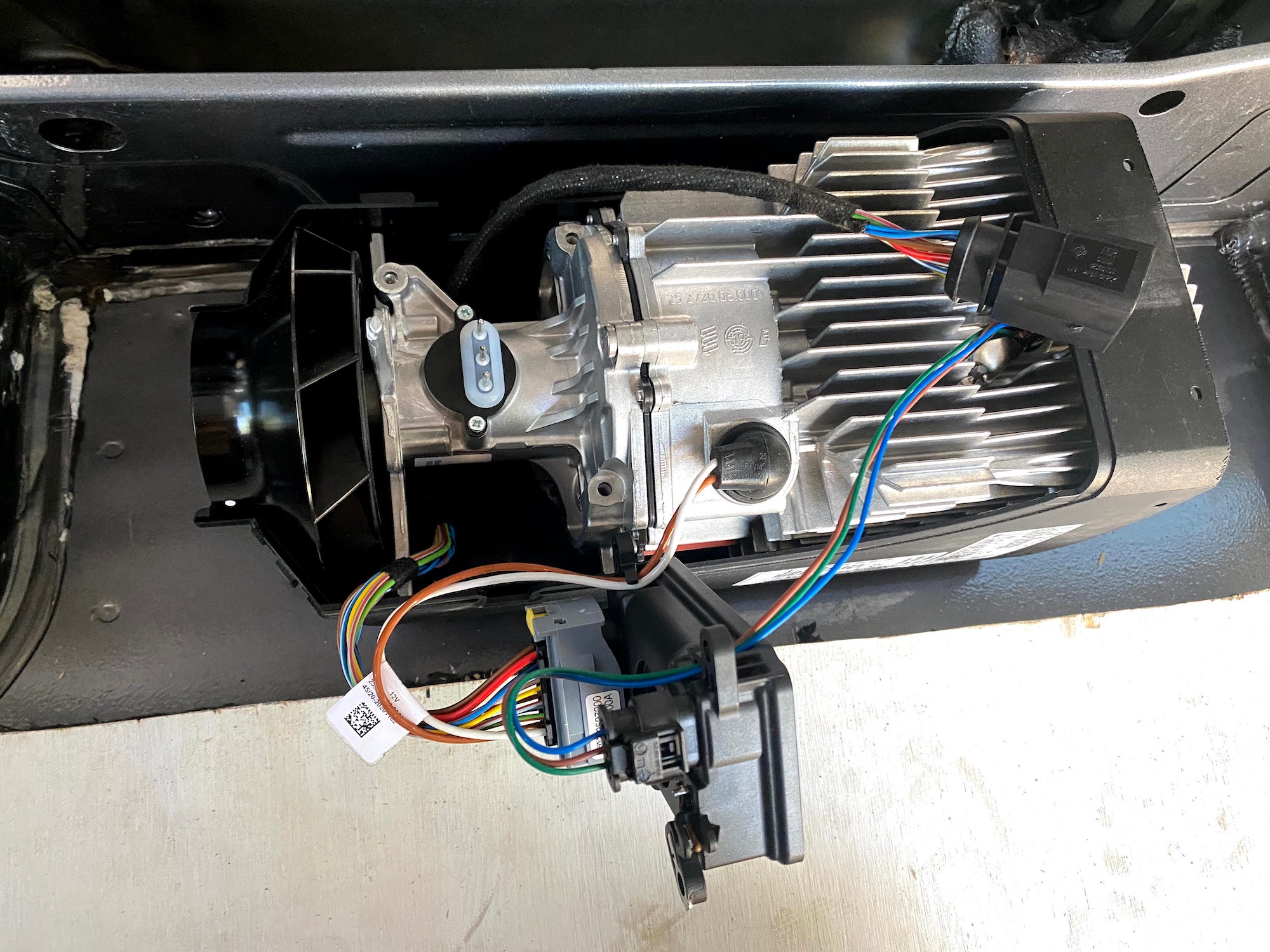
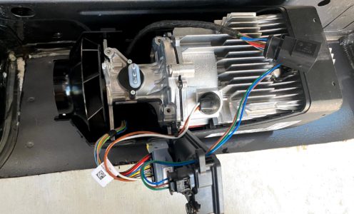
In our Sprinter, the heater was installed in the passenger seat pedestal. I chose a different location for the B4L for a couple reasons; 1) The B4L is slightly larger than the D2 and the Transit seat pedestal being smaller than the Sprinter. 2) The location of the van essentials that are under the van beneath the passenger seat. It seemed that the effort to install the heater there was going to make a difficult job far more difficult.
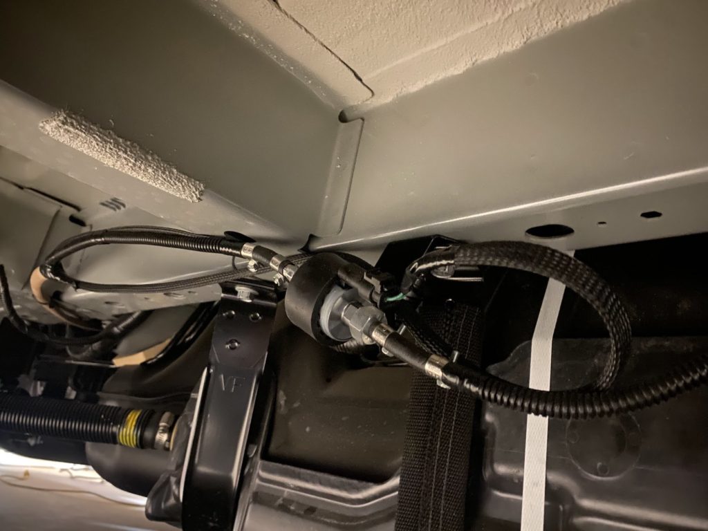
I decided to install the heater on the floor of the van just in front of the driver side rear wheel well. The underside of the van is clear of any obstacles in this area. Added benefits of this is that the warm air output is more central to the living area of the van and the length of the fuel line between the gas tank and the heater can be minimized. As you’ll see later in this post, gas can be a troublesome fuel for this type of heater system and the shorter the fuel line, the better.
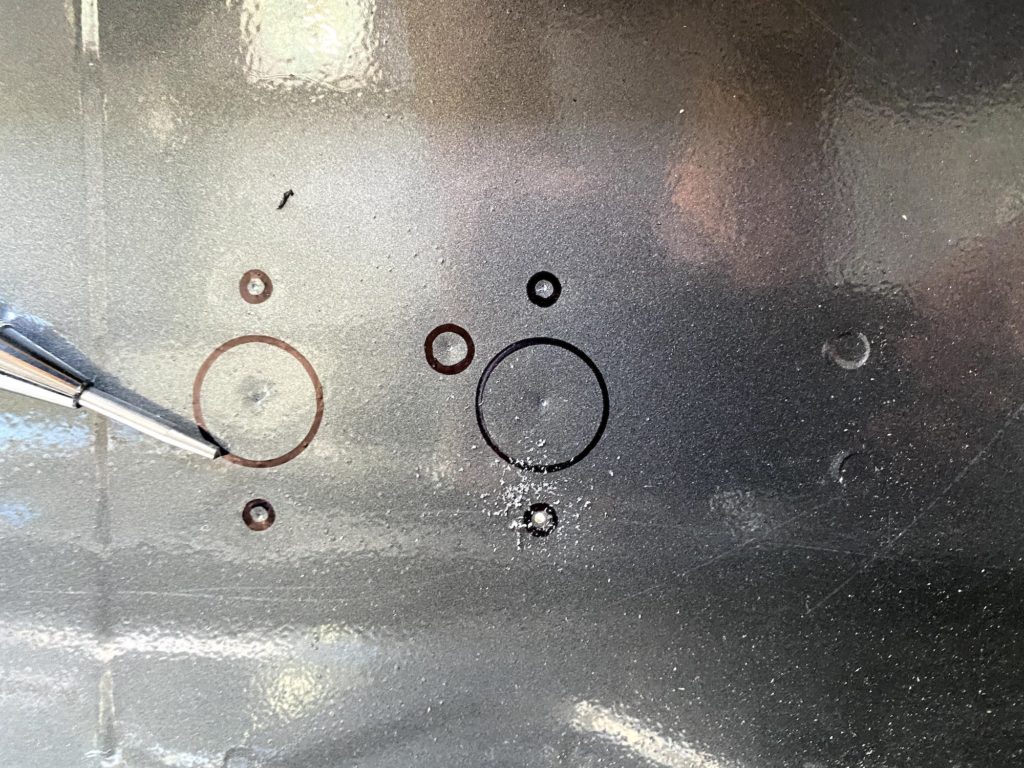
The kit comes with a metal baseplate that is very useful as a template for drilling holes in the floor. Drill the holes and paint them to prevent corrosion. With the holes drilled and protected, be sure the rubber grommet is on the underside of the heater and set it in place. From the underside, install the washers and then thread and tighten the nuts onto the threaded posts. Since the floor in the van where I installed the heater is flat, I didn’t need to use the base plate.
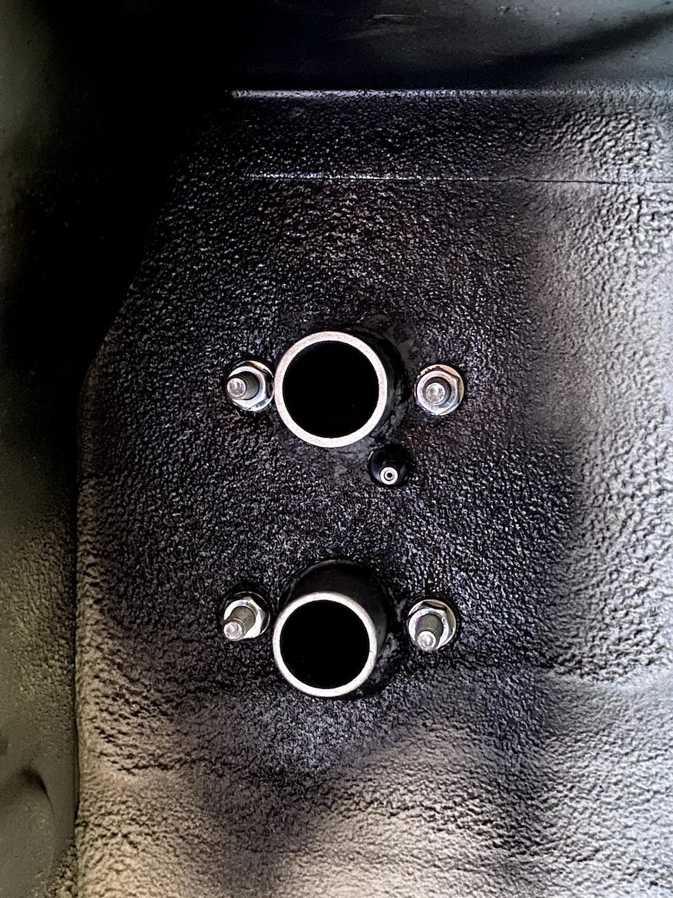
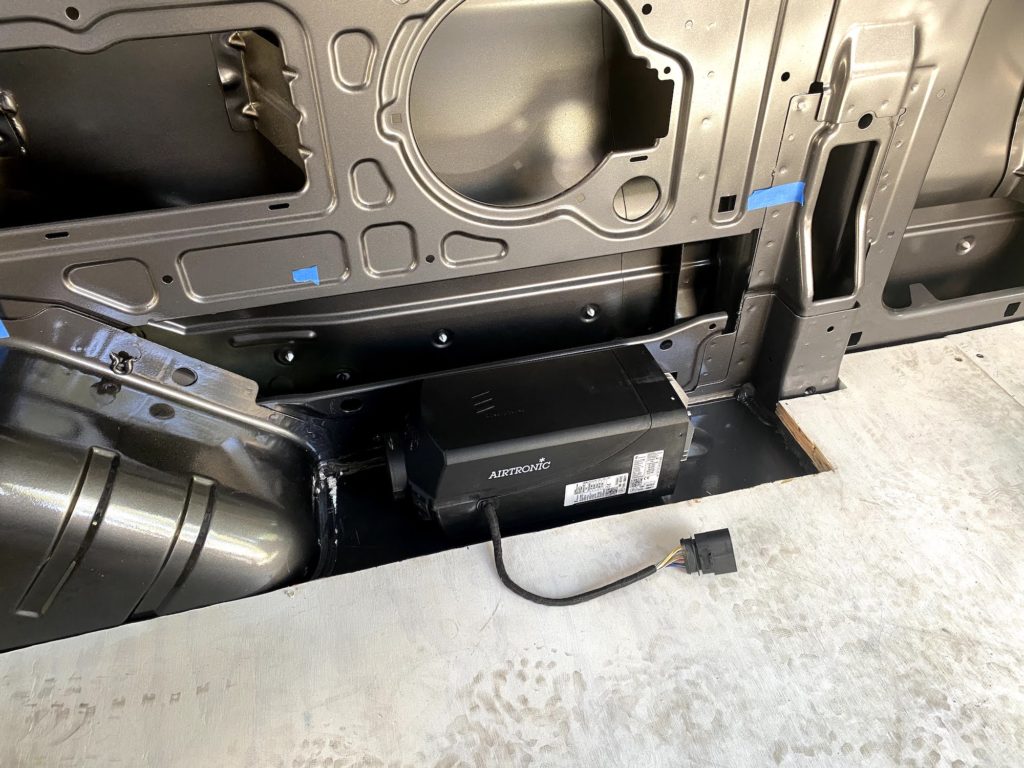
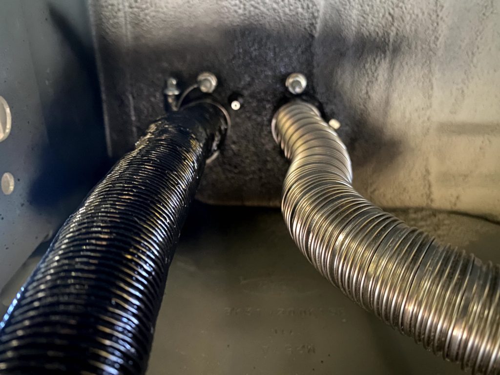
Once the heater is in place, connect the combustion air intake and exhaust hoses. The air intake is the black hose and the exhaust is the shiny metallic hose. Note that the side with the fuel pickup port is the air intake side. Then route the air intake hose to a protected area where debris and exhaust will not get pulled in. The exhaust should be kept short and away from anything affected by heat. The end should clear the side of the van so no exhaust fumes can collect under the van.
Fuel Source Install
The fuel source install was a day I was dreading for months and had expected to be the most stressful job on the entire camper van build. At the end of the day, the install was successful but there were a number of challenges along the way that added to the stress.
There are three things to do when planning your fuel line run from the fuel tank to the heater to mitigate cavitation; 1) install the fuel metering pump as close to the fuel tank as possible to have the shortest amount of fuel line on the supply or pull side of the pump. 2) install the fuel metering pump and fuel lines away from any heat sources like the heater exhaust. 3) install and use the Espar provided fuel standpipe and not the Ford provided auxiliary fuel pickup on the fuel sending unit.
Special tools to have onhand:
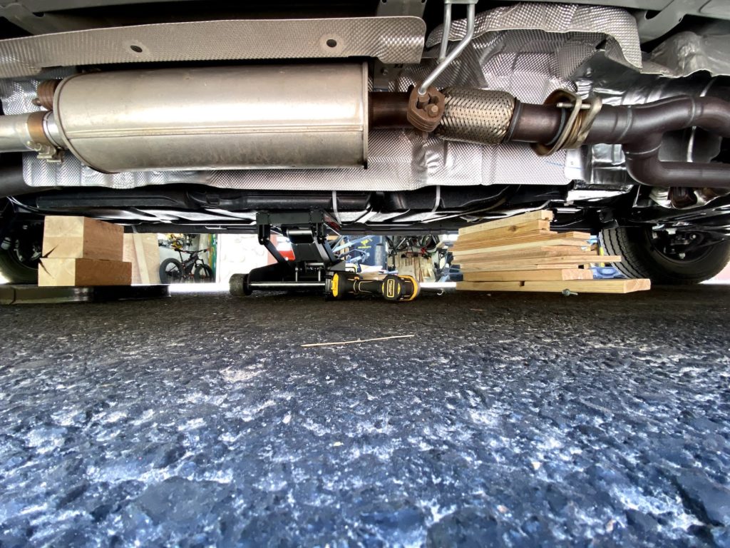
In preparation for doing this phase of the install, you’ll want to run the fuel tank as empty as possible. The less gas in the tank, the easier it will be to manipulate. Dropping the tank is fairly simple; support the tank with something so it doesn’t fall while removing the supports and then remove the bolts for the metal straps supporting the tank. I used an ATV jack and stacks of scrap wood. Pay attention to the lengths of the bolts as there are two different size bolts.
It is optional to remove the fuel filler hose. I didn’t but it probably would have been easier if I did. With the tank lowered, you now have access to the fuel sending unit.
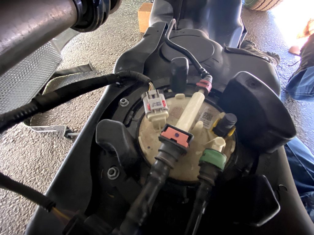
With access to the sending unit, remove the electrical connector and the 3 fuel lines. The largest of the fuel lines is a bit tricky, using the fuel line disconnect tool makes that easier. Next, the ring cover can be removed, be sure to pay attention to the orientation before removing it to make reinstallation easier.
Using the fuel pump lock ring tool, the fuel sending unit can now be removed. Note the orientation before removing the fuel pump. Turning the lock ring took far more force than I had expected. I was concerned about breaking something using that much force, but alas, nothing broke and the sending unit was now free. Removing the sending unit required a bit of twisting and turning due to the float arm that extends beyond the opening in the fuel tank. Be very gentle with this step as you don’t want to break the float.
Installing the standpipe
Modifying the sending unit to install the standpipe is a matter of finding a safe location to drill the hole where the standpipe will not interfere with any of the sending unit functionality. I put mine above the float and put a slight gentle bend in the standpipe to ensure there is space between the standpipe and float. I cut the length of the standpipe to be short enough that it won’t touch the bottom of the fuel tank when the sending unit is compressed vertically.
The standpipe comes with plastic line inside its length. This is just protection material and you should discard before use.
The fuel sending unit is reinstalled into the fuel tank. Be sure to recall the orientation. The sending unit will need downward pressure while installing the lock ring. Again, the lock ring will need considerable force to get it to go back into place. The lock ring cover goes back next, ensuring the proper orientation. Reattach the van fuel lines and electrical connector. Lastly, connect a length of Espar fuel line to the new standpipe using the short rubber connectors and fuel line clamps. With the sending unit and fuel tank reassembled, raise it back into place and reinstall the metal supports. Pay attention to the new fuel line as you raise the tank back into place. Be sure that it does not get pinched and is leading to where you you want it to connect to the fuel pump.
Optionally, you can add protection to the fuel line by using 3/16″ inner diameter rubber fuel line or 1/4″ split loom and running the Espar fuel line through it.
Fuel Metering Pump
The fuel pump gets installed into the rubber mount and that gets bolted to the steel odd shaped bracket. I mounted the steel bracket to one fuel tank support bolts, this location allows for about the shortest run on the pull side of the pump. Pay attention to the direction of the fuel pump input & output sides. Be sure to angle the pump so that the output side is higher than the input side.
The last bit of this is to run the fuel line from the fuel pump to the heater, ensuring that you avoid heat sources and any parts that move.
Wiring Harness and Power
At first glance, the wiring harness is quite daunting. The Espar documentation could be better. This video does a good job of explaining the different connections of the harness. He is using a diesel heater, but the wiring harness is the same for the M2 B4L. Watch on Youtube.
This image also sums it up:
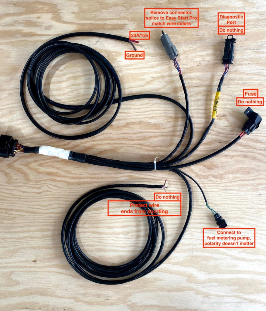
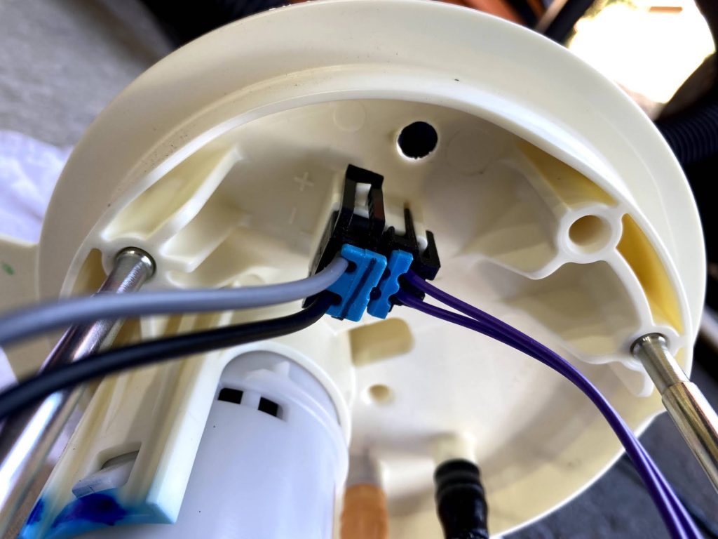
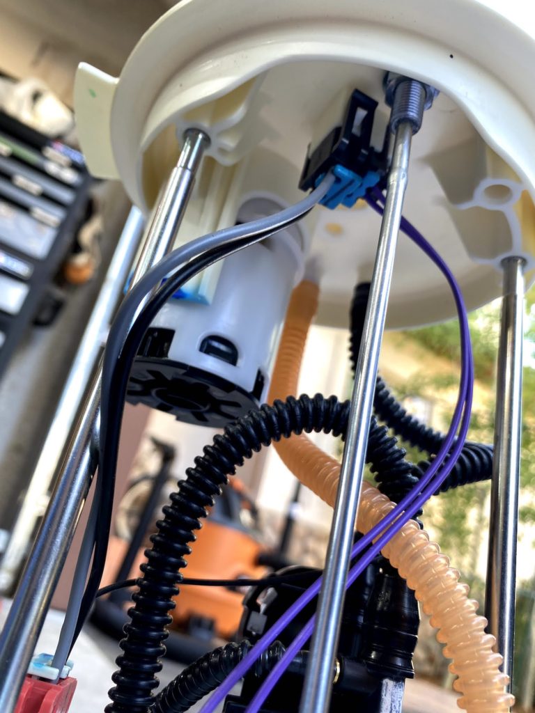
The heater kit comes with a couple different connectors & pins for those connectors. I don’t have the proper crimping tools and didn’t want to purchase them. Also, if I screwed up the crimp, I would have to find a source for new pins. Or worse, if I screwed up a crimp and didn’t know it, I could end up with a bad connection. I chose to cut the connectors off and splice the wires.
Heater wire lead position
Depending on where you installed the heater, it might be convenient for the heater’s main wire connector to come out of the opposite side of the heater. To do so:
- pop off the cover to the inlet end of the heater
- remove the 3 screws securing the ECU
- lift the ECU straight up and off the 3 connecting pins
- feed the wire connector under the fan shaft
- swap the rubber grommets on the two slots on the side of the plastic housing
- reverse the process to put it back together.

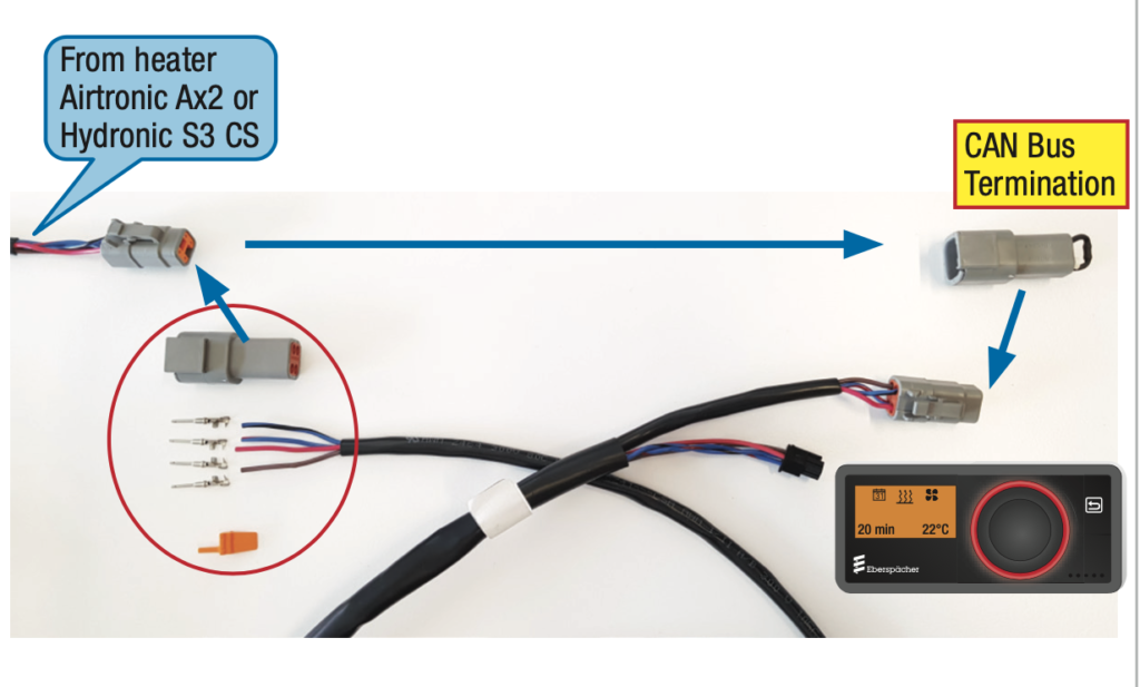
A key thing to note on the wiring harness. There is a cap with the 120Ω resistor on the EasyStartPro branch of the harness that must be moved to the EasyStartPro harness connector. This is one of the most common errors made in the installation process according to Espar support.
Troubleshooting
I have to say that the folks at Espar were very helpful and responsive. Contact info:
- help@eberspaecher.com
- help.espar@gmail.com (as of this writing, Espar’s IT infrastructure was impacted by a hack but the support folks are using this gmail account as a backup)
- phone: +1 905 670-0960, ext.2299
- Get most up to date technical documents here: Eberspaecher Documentation Portal
Problem Determination
Problems with the heater generally fall into one of 2 categories; 1) fail to start 2) stopping prematurely
Causes of the problems also fall into one of 2 categories; 1) fuel delivery 2) electrical
In the problem category, I was fortunate enough to experience both categories; fail to start and once that was resolved, I got to deal with an issue where the heater was stopping prematurely.
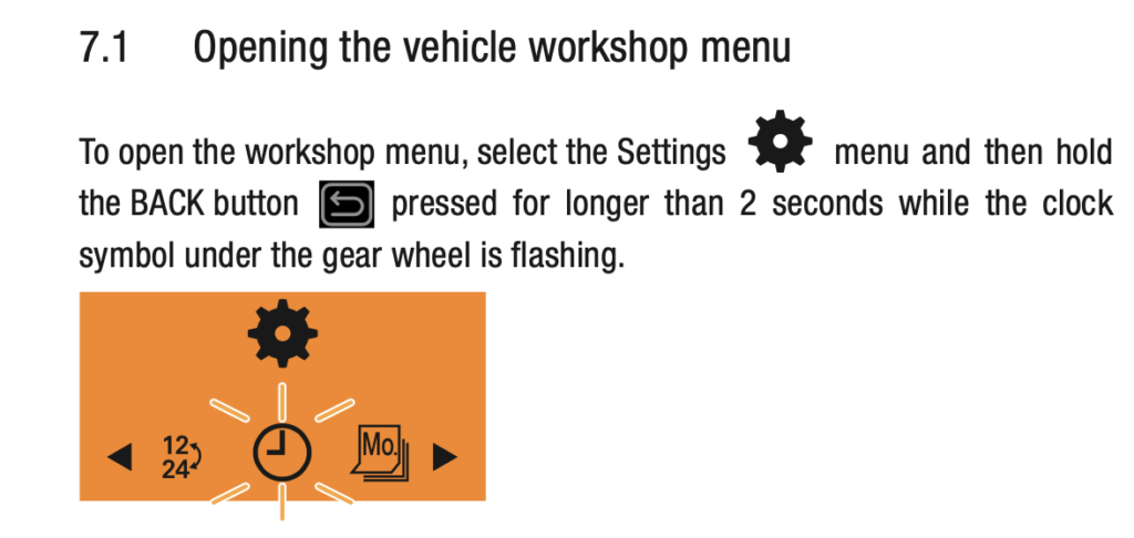
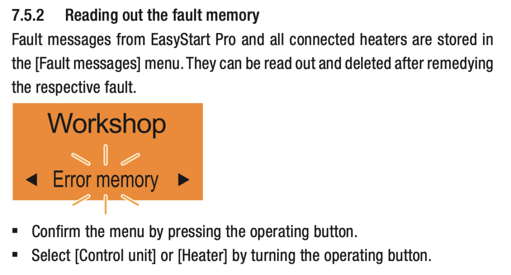
The first thing you need to do when experiencing any kind of problem is to read the fault code(s). This is done through the EasyStart Pro controller by getting into “workshop” mode.
Once you have your fault code, you can determine the problem by looking it up in the document below. Depending on when you are reading this, you may find an updated version of this document on the Espar document portal.
Testing
The first problem I encountered after installation was a P000223 fault. This fault indicates the impeller might be blocked. While the heater would not start, the fan would run fine in the vent mode. This made no sense to me so I reached out to Espar support. They asked some questions about the physical install and software versions. They determined that the firmware that was flashed into my ECU was the for the wrong Espar heater. I sent the ECU to Canada to be re-flashed. About 7 days later, I had the updated ECU and the heater would now run. It was summer and I tested the heater for about 10 minutes at a time to see that it would generate heat and was satisfied that the heater was working and the install was correct.
Fast forward a couple months, and I attempted to run the heater for a longer period of time. The heater would run fine for between 15 and 30 minutes before shutting down with a P000129 error (Flame cutout within the control range 75% – 100%). Little did I know that this would be the start of nearly 4 months, on & off, to determine the cause and resolution.
The P000129 is one of 5 related flameout errors (P000125-P000129) with each one denoting a different state of the heater when the flameout occurs. The P000128 & P000129 are generally fuel related while the others are generally electrical.
Power System
The Espar support folks raised a concern that I am using a lithium battery to power my electrical system. They explained that they have seen issues with lithium batteries and requested that I try a lead-acid battery. They admitted that they don’t know why this is but since there was no explanation for the problem I was having they wanted me to try it. I addressed this 2 ways; 1) a temporary12v power supply to power the heater and there was no change in the heater behavior. 2) I purchased a step down voltage regulator that accepts the higher voltage of a lithium system (normally 13-14.2v) and produces 12.44 volts. This also did not change anything.
Electrical Interference
I later learned that the concern about the lithium battery systems has more to do with the typical charging systems than the battery itself. The Espar wiring harness follows the CAN bus standard, but the standard does not dictate the all of the mechanical aspects. As such, Espar uses twisted pair 2 wire bus as specified by the CAN bus standard but chose not to use shielded cable and, as a result, is susceptible to electromagnetic interference.
Should the Espar wiring harness be physically located close to any high current or otherwise electrically noisy wire or devices, they can cause interference with the Espar system. The charging systems generally have wires and components that fall into this category. The result of the interference could cause any number of intermittent or even non-intermittent failures of the heater. Zip tying the Espar wiring harness to any other wiring is also a no-no. In my case, the Espar wiring harness follows a path that is not near any other wires or devices.
Wiring Harness Validation
One way to validate that the wiring harness is installed properly is to check the resistance between pins 1 & 3 of the main connector on the harness itself. This should read 60Ω within 2Ω. In my case, it read 120Ω. The cause of the problem was that I did not move the CAN bus termination cap to the EasyStart Pro wiring harness as highlighted above in the “Wiring Harness and Power” section above. I installed the cap and the reading changed to 60.2Ω. With this corrected, the heater still operated the same.
Air Intake
Another concern was that maybe the air intake could be obstructed. I removed the air intake hose, visually inspected the intake port for any obstructions and then tested the heater without the air intake hose in place. No change.
Fuel Delivery
The physical and electrical aspects of the install seemed to be good at this point, so the issue must be with fuel delivery. Fuel delivery issues can be summed up simply as either too much or too little fuel. The heater ECU will send electrical pulses to the fuel pump to provide the proper amount of fuel. The rate of pulses are determined based on how high the heater is running and the heater will adjust this based on altitude.
One of the challenges with using gasoline as the fuel source is that chemically, it has weak intermolecular bonds so that it easily cavitates compared to other fuels like diesel and kerosene. The warmer the temperature and the less pressure, the more likely it is to cavitate. The fuel metering pump pulls fuel from the fuel tank and pushes the fuel to the heater. The pulling action creates negative pressure which encourages cavitation. The heater can tolerate some cavitation but when it becomes excessive, the heater will flameout and shutdown with a fault. Essentially the vapor caused by the cavitation replaces some of the liquid gasoline and the heater is starved of fuel.
Fuel Line Connections
Be sure your fuel lines are fully inserted into the fuel line connectors. Moistening the fuel line will help make the insertion into the connector easier.
Fuel Quantity Test
Working with the Espar support folks, they requested a fuel quantity test to validate that the heater and fuel pump are delivering the proper amount of fuel. This is where I disconnect the fuel line from the heater and direct the fuel line into a graduated cylinder. Then start the heater and measure how much fuel is provided between the time that the heater is started and shuts off the first time. The heater will attempt to restart due to the failed start with no fuel. Only the first attempt to start is to be measured. My result was at the low end of the normal range.
Gas Can Fuel Test
To determine whether there is an impingement between the fuel tank and the fuel pump that may be restricting fuel flow, I used a gas can as the fuel source. To do this, disconnect the fuel line at the input side of the fuel pump and place a new length of fuel line to the pump and put the other end in a gas can filled with gas. There was no change in the fuel quantity test or the behavior of the heater with this test.
Fuel Filter Test
A theory that was offered was that the fuel filter could be defective or blocked. If this were the case, the additional resistance could impact the pump’s ability to properly deliver fuel to the heater. I removed the fuel filter from the inlet side of the fuel pump and ran the tests again. There was no change, so we can conclude that the fuel filter was fine. Unfortunately, I destroyed the filter while removing it. Here is a video showing the proper way to remove the fuel filter: https://www.youtube.com/watch?v=Cq7DjxWU7oE
Kerosene Test
Another test that was suggested was to repeat the gas can fuel test with kerosene for 30 minutes instead of gas. The point of this is to narrow down the cause of the problem. Kerosene is far less likely to cavitate and should have run longer than my heater was running with gas. This would help validate that the heater itself was functioning properly and that the problem was indeed with delivering fuel to the heater.
Heat Exposure
With all the validation done to this point, we’re starting to run out of ideas. I had run a heater test on a very windy day and the heater ran for hours until I shut it down without any error. Ah ha! I then tried it on a calm day and the heater shut down with the P000129 fault again. I placed a leaf blower under the van directed at the underside of the heater and it once again ran indefinitely. With this, I began taking temperature readings under the heater. The readings in the image below are shortly before the heater shut down with the fault.

With this information, the support guys sent Mike, the lead Espar trainer, my way. We talked through everything that has transpired so far. He enlightened me on the wiring harness validation test mentioned above. With heat being the smoking gun at this point, we looked at mitigating the heat exposure to the fuel lines, especially the last few inches before entering the heater.
I put a length of 3/16″ inner diameter fuel line rubber hose to sleeve the Espar fuel line, no change.
I wrapped the sleeved fuel line with heat shield material, no change.
Fuel grade
Mike had asked what grade of gas I use, which is 91 octane which is recommended for the EcoBoost Ford Transit. He suggested that I try 87 as lower octane gasolines have less oxygen in them and might be less prone to the affects of the heat. I queried the folks on the Ford Transit Forum about this and across the board folks are all using 87. Apparently, I was the only one wasting money on the premium grade gas. I also noticed after a few tankfuls of 87 that my gas mileage improved a smidge. Unfortunately, there was no change in behavior for the heater.
Espar EasyScan Diagnostic Unit
Right about this time Mike was scheduled to do some training sessions in the Denver area. He arranged to have the heater in my van to be used for training. The kind folks at Adventure Vehicle Concepts agreed to this arrangement and I was set to have Mike and some experienced installers all checking out my first-time heater install.
Mike connected the EasyScan diagnostic tool to my heater while explaining the how the EasyScan tool works and showed the trainees all the gotchas with both the tool and heaters in general. My heater passed the extensive diagnostic tests that the EasyScan tool provides.
EasyScan real-time diagnostics
Next, we fired up the heater and had the EasyScan display showing an impressive array of heater sensor readings and statistics. The key value Mike focused us on was the internal temperature and he predicted what was going to happen. We watched as the temperature climbed and the heater got itself up to speed and was producing heat very well. About 15 minutes in, the internal heater temperature began to slowly fall and continued to fall until the heater shut itself down and produced the P000129 fault code.
Another key metric we watched was input voltage. I have a voltage regulator in place that provides 12.44v regardless of the lithium battery voltage which generally ranges from 13.5v – 14.1v. As the heater started and really got cranking, the voltage did briefly drop to about 11.5v. If it dropped much lower, we could have gotten a low voltage fault. Mike recommended moving the heater’s power lead closer to the battery instead of having it in the power distribution panel.
The smoking gun!
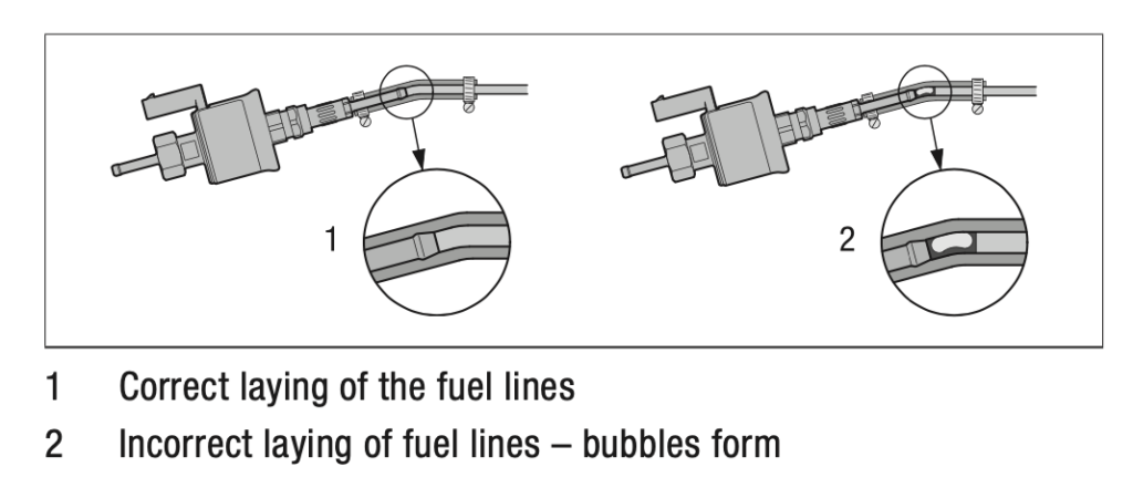
So why did the P000129 fault happen? Gas enters the fuel pump in fully liquid form as it is pulled from the fuel tank. As the gas passes through the fuel pump, gas will cavitate at the piston of the pump and some vapor will be produced along with the liquid gas. The gas will appear to have bubbles in it as it is pushed to the heater. This can be observed in the translucent fuel line between the pump and the heater. As the ratio of vapor to liquid increases, the total amount of fuel provided to the heater is reduced. As more heat is introduced, the vapor expands further, the total amount of fuel to the heater continues to drop essentially starving the heater of fuel causing the flameout and shutdown.
Resolution
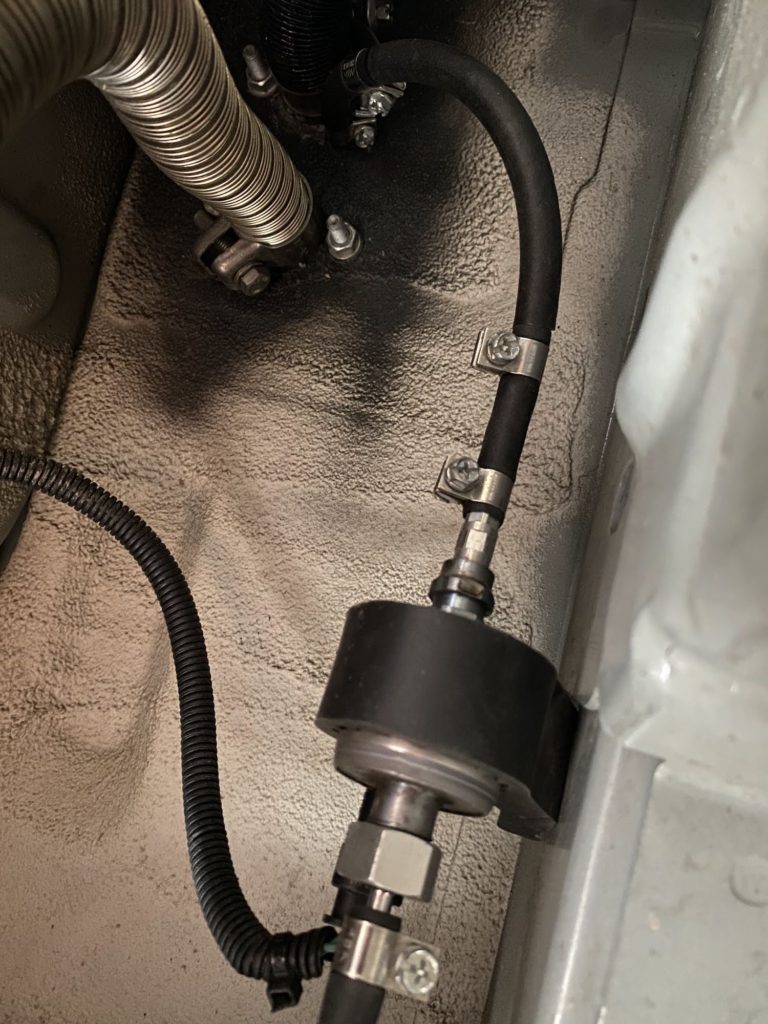
I had my pump mounted on the side of a frame rail under the heater close to the underside of the van floor. The frame rail along with other frame components create an air pocket under the van where heat could build up under the heater. The AVCRIG guys showed me how they mount the fuel pump right next to the gas tank on one of the gas tank support bracket bolts so that it is just below the frame rail. This location has the benefit of shorter fuel line on the pull side of the pump as well as much more airflow around the pump.
The pump itself cannot be insulated against external heat sources. The pump is a heat source and the heat it generates needs to be dissipated. It is best to mount the pump where there is plenty of airflow.
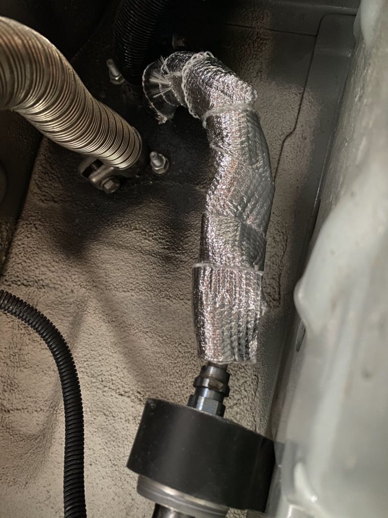
The training session ended and I went home with homework to move the fuel pump to the location that ACVRIG prescribes. For good measure, I also shortened the combustion exhaust line to get the heat from the exhaust out from under the van as soon as possible.
After making these last two changes the heater has operated flawlessly up to 11,000 feet of elevation.
Warm air output duct (or lack thereof)
This is an issue and accidental resolution discovery that came up after my issue was resolved. It seems that the combo sensor on the Espar M2 B4L may be too sensitive to low temperatures and shuts down with fuel delivery fault codes (P00012a, P000128 and/or P000129) on installations with no output ducting, such as when the heater is installed in the seat pedestal. The working theory is that the output duct slows the airflow just enough for the temperature sensor to better detect that the heater is starting to warm up and thus allow it to continue operating. Without the back-pressure, the warm air flows out of the heater too quickly and the heater is fooled into thinking that it is generating no heat. In my case, I have about 36″ of output duct with a gentle 90° bend that seems to provide the back pressure that allows the temperature sensor to detect the heated air.
The accidental discovery of the workaround is that someone that had been experiencing this issue had left a backpack in front of the heater warm air output and the heater did not produce the fault and he put 2 & 2 together as to what the cause and resolution is to this issue. Shortly after, another forum user with the same symptoms confirmed this as a workaround.
Personally, I believe this to be a defect with either the sensor or the firmware logic processing the sensor data. The fault codes in this case are completely misleading to what is actually happening and the firmware is making a very bad assumption. The Espar D2 heater that was in my Sprinter had no output ducting and did not exhibit this issue.
Additional Resources
- https://www.letonkinoisvarnish.co.uk/eberspacher_fuel_1.html Some good background on various Espar heater issues
- https://www.fordtransitusaforum.com/ Search for “Espar” on this forum
- https://sprinter-source.com/forums/index.php Search for “Espar” on this forum
- https://www.eberspaecher-na.com/download-center/technical-manuals Espar technical document portal
- A forum post on Espar installation with additional detail and pictures

Send us a message:

Wow…..just wow….what you went through to get a working heater is almost beyond comprehension. But you got it done!
I did a first time diy install of a B4 with altitude kit in a Promaster using the factory fuel tap and it’s been without flaw for three winters.
Even at high elevations…I spent four nights getting snowed in last spring at Montgomery Pass CO at 11k….heater ran nearly continuously on low. Numerous nights on Burthoud, Winter Park, Copper, etc….it just goes. Hopefully, the party continues.
How has your heater been holding up?
Thanks Tom, I’m glad you got your heater working straight away. Mine continues to operate flawlessly since moving the fuel pump.